autocad raster design tutorial video
A very cool AutoCAD add-on called "Raster Design" lets you easily incorporate raster images like .jpegs and .tif files in you drawing. The cool part about this software is that it lets you edits the images even though they are pixelated images. You can even convert these pixels into AutoCAD entities for editing using you normal AutoCAD commands and then when you need to present the edits in a PDF, you can change the AutoCAD entities back into the pixelated form so that they match the rest of the image.
Shown below is the Raster Design 2014 ribbon tab:

Raster Design 2014 Ribbon Tab
Let's get started:
- INSERT AN IMAGE – Using the "Insert…" tool located on the far left of the ribbon, you can navigate to the image that is to be brought into the drawing. The command line version for this tool is IINSERT <enter>
Note: The terminology is a little confusing because usually images are brought into AutoCAD with the ATTACH command and blocks are usually the only things that are "inserted"…

- Browse to the image.
Notice the options at the bottom of the screen. The 2 shown below are asking how you want to be prompted for various settings while inserting the image. If you want to take the default settings, click "Quick Insert"

Once the image is in your drawing, you may need to re-position and scale the image to fit your needs. You can scale it by using the SCALE command or by dragging one of its corners to shrink or expand the image. To move the image, use the MOVE command.
IMAGE TO BITONAL – Many of the tools in Raster Design only work if the image is "bitonal" (black & white). Shades of grey or color images simply wont work well in Raster Design. To make the image "bitonal" click on the "Process Image" drop-down > then click "Change Color Depth" > then B <enter> in the command line to choose the "Bitonal" option.

INVERT COLORS – Now that the image is in your drawing in black & white, you can change the colors so that you are working in a more familiar color scheme. You can easily invert the colors so that the lines are white and the background is your normal AutoCAD background.
Click on the "Cleanup" drop-down > then click "Invert"

(shown below: image colors inverted)

DESPECKLE – The little speckles that are present in the drawing from the image can be easily cleaned up and make your editing look that much cleaner (and easier to edit).
Click the "Cleanup" drop-down and then "Despeckle"

You are then asked to specify an area of the image that you wish to clean up. For this example I used I <enter> to clean the entire image.
Note: I did notice that on a few drawings, it erased some periods and commas in text that was in the image. So be aware that those may come across as "speckles" and may be cleaned.
![]()
You are then asked to specify the size of the speckle so that it will look for similar sized speckles and clean them up. You can do this by either picking within a speckle or by making a window selection. when you are done, the similar sized speckles that are found are highlighted in red and you are prompted to accept the selection set of what it is about to clean up.
MANUAL TOUCH UP – You may need to manually touch up the drawing. For this, the "Touchup" tool allows you to manually erase or draw sections of the image similar to Microsoft Paint allows you to draw with a few pixels at a time.

- Toggle the color of the "Touchup" tool to either black or white by clicking "Toggle drawing color"
- The shape of the brush can be defined by the tools on the left side of the tool bar.
- The angle of the brush is also defined on the 3rd tool from the left
- The size of the brush can be changed by clicking the button shown below. This will let you define the size by either dragging a window or by entering a number.

To exit the Touchup tool, use the buttons on the toolbar to CANCEL or OK to accept the edits.

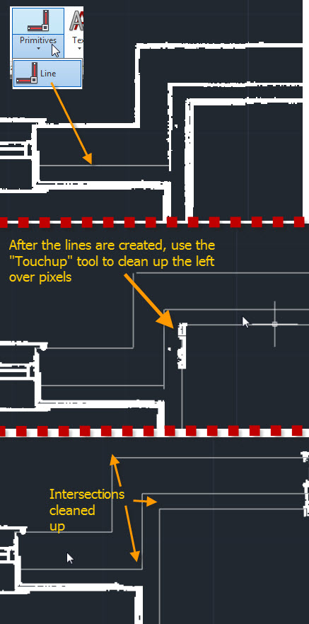
CONVERT PIXELATED LINES TO VECTOR LINES – This allows you to make edits with your familiar AutoCAD commands. In the example below I only show how to use the tool that recognizes lines. There are other tools that recognize arcs, circles, polylines and rectangles.
On the "Vectorize & Recognize Text" panel, click the "Primitives" drop-down and then select "Line"

- Place the cursor within a line in the image. If the line is recognized, a dashed line will appear that has a little yellow arrow (glyph). To accept this, hit <enter> and the pixelated line will be turned into an AutoCAD line and the pixelated line will be erased.

When using this to recognize lines that should meet at their corners, it may not work as precisely as you'd like, but you can clean them up by using FILLET with a ZERO radius.
You may also need to use the Touchup tool to clean up left over pixels…

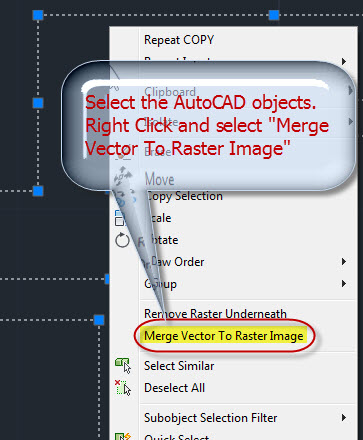
Once the edits have been made, you will need to plot the drawing but the AutoCAD lines will look so different from the rest of the image. To change the AutoCAD lines back into "Raster" simply select the AutoCAD objects and then right click > select "Merge Vector To Raster Image"

The AutoCAD objects will now match the Raster objects in the image

MANAGING THE IMAGE FILE (EMBED) – When you bring an image into a drawing, AutoCAD treats the image as a reference. that means that there will be 2 files needed in order for someone else to see the same thing that you see. Luckily, you can easily embed the image so that it is in the .dwg file so you only need to send someone the one file.
On the "Insert & Write" panel, click the "EMBED" tool and in one click, the image is now embedded in your drawing.

autocad raster design tutorial video
Source: https://autocadtips1.com/2013/09/19/raster-design-quick-start/
Posted by: nelsoncovelf.blogspot.com

0 Response to "autocad raster design tutorial video"
Post a Comment